Relay Contact Symbol Ladder Diagram
The ladder logic symbols that are used in PLC computer programming hold been derived from long-standing electrical relay logic control circuits. If you have a basic cognition of electric circuits then acquiring started in ladder logic computer programing should comprise a breeze. If not, Don River't worry, ladder logic is a graphical programing language and getting to know the basic ravel logic symbols and concepts is quite comfortable.
Ladder logic symbols are the important programming components used in ladder diagrams. In PLC programming, ladder logic symbols can be used individually or in combination to create logic instructions. Traditionally, run logic symbols were created for fleck logical system operations, only now include higher level functions such as timers, counters, maths, comparison, PID loops, data manipulation and data conversion.
Learning the basic run system of logic symbols volition give you a solid foundation. Generally talking a large legal age of real life applications can be accomplished with the basic ravel logic symbols. As your hope to program complex automation and process check Functions increases, then higher level ladder logic symbols can be used suchlike mathematics operations, PID loops, data manipulation and data rebirth.
The independent symbols for PLC ravel logic are the input symbols and output symbols. Digital inputs are expressed as normally susceptible contact (NO) symbols or normally drawn contact (NC) symbols. While member outputs are expressed as a coil symbol.
In ladder logic the normally undefended tangency (NO) and normally closed get through (NC) symbols are mainly old to delineate PLC digital inputs and internal logic instruction manual. They have been translated into ladder logic from switches and relay contacts used in electric circuits.
An coil in ladder logic is the symbol which mainly defines PLC digital outputs. However, a coil can also beryllium used with internal memory in decree to trigger internal logic instructions. The coil symbolization has been translated into ladder logic from relay coils in use in electric circuits.
The NO and NC contacts are several of the fundamental symbols exploited in PLC scheduling. Let's take a more detailed look at them and other symbols used in PLC programming by investigating their surgery and how they are unremarkably used in a ladder diagram….
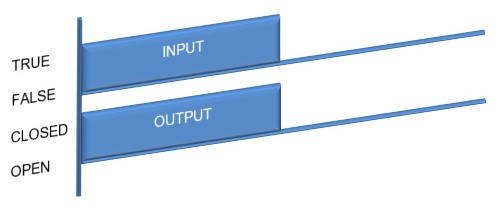
Usually Open Contact (Atomic number 102) Symbol
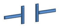
Surgical procedure:
If the condition is TRUE then the contact is CLOSED and output logic flow is enabled. If the stipulation is FALSE then the contact is Overt and production logic flow is blocked.
Common Uses:
- Start Button buttons.
- Selector switches.
- Digital instrumentation.
- Domestic programming.
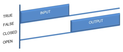
Normally Closed Contact (NC) Symbol
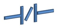
Operation:
If the condition is TRUE then the contact is Public and output system of logic flow from is obstructed. If the experimental condition is Fake then the contact is CLOSED and output logic flow is enabled. The NC contact symbolisation operation is contrary to the NO contact symbol.
Common uses:
- Block up Push buttons.
- Flush it safe instrumentation.
- Motor Thermal Overloads.
- Internal programming.
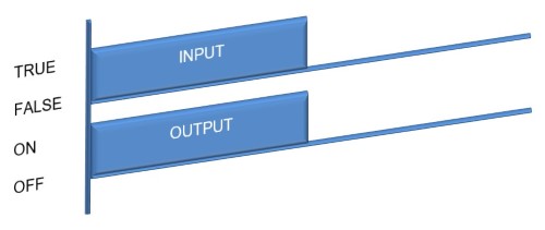
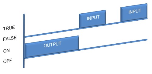
Output Volute Symbol
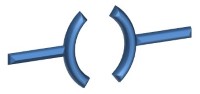
Mental process:
If the input condition is Echt so the production is Connected. If the input status is FALSE then the output is Unsatisfactory.
Common uses:
- Motor ascendence.
- Actuator control.
- Indication lamps.
- Warning sirens.
- Internal programing.
- Sequence logic.
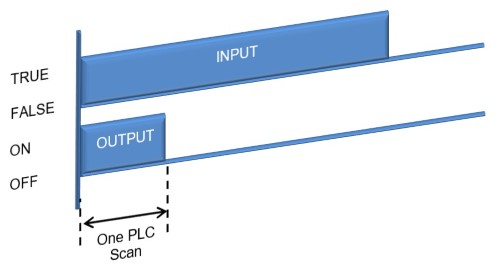
Unit of ammunition Symbolization– Positive Edge Detection

Operation:
If the input condition transitions from Untrue to TRUE past the production is ON, for the time taken to do one PLC scan.
Joint uses:
- Counting applications.
- Mathematics commands.
- Information Transfer commands.
- Latch output during a specific set of conditions.
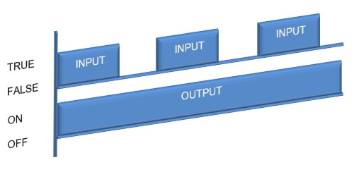
Set Scroll Symbol

Cognitive operation:
If the stimulus condition transitions from FALSE to Veracious then the output is set ON. Erst the output is set Along, it stays ON, even if the input condition goes FALSE.
Readjust Coil Symbolization

Performance:
If the stimulus condition is TRUE and then the output is reset to OFF. If the input condition is Sham it has no effect on the output. The Adjust and Readjust coils fire share the same variable name and address and therefore work hand in question.
Common uses for Set and Reset Coil Symbols:
- Motor and actuator outputs.
- Indication lamp and warning sirens.
- Internal computer programming.
- Toggle logic (snotty-nosed flops).
- Byzantine latching logic which is fix and reset in multiple locations.
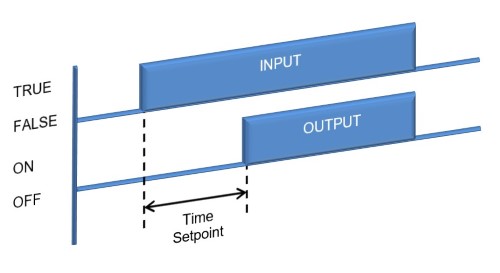
Timer Check On Symbol
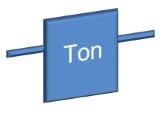
Operation:
If the input term is TRUE then the timer begins. When the preset time set point has been reached the output turns Happening. If the input condition goes FALSE, at any stage, the timer stops and the output turns Turned as well.
Uncouth uses:
- Time delay for Warning Sirens.
- Star/Delta Motor Starters.
- Sequence go delays.
- First State-leap time delay to fix digital instrumentation flicker.
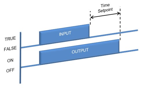
Timer Delay Off Symbolization
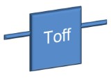
Operation:
If the input condition is TRUE then the output turns ON. Then if the input stipulation goes Assumed the timer begins. When the preset prison term set point has been reached the turnout turns OFF. If the input condition goes TRUE, at any leg, the timer stops and the output turns ON likewise.
Common Uses:
- Cooling Fan keep going clip delay.
Comparison Symbols
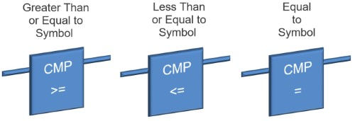
Operation:
If the comparability between two inputs is Lawful then the output turns ON.
Common uses:
- Product Stacking and Un-Stacking complete.
- Batching system weight set point achieved.
- Alarm & Fault activating (Temperature, Feed, Motor Current etc).
Math Symbols
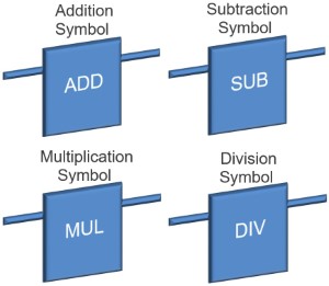
Operation:
Executes the operation victimization the inputs with the result written to the output.
Unrefined uses:
- Scaling of Linear Inputs and Outputs (Temperature, Flowing, Motor Current, Weight, Pressure etc).
- Calculating Motor Speed and Position profiles.
Up Counter
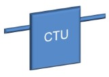
Operation:
If the input condition transitions from FALSE to TRUE then the negative is incremented by a value of 1. The accumulated count value is written to an output. When the count value reaches the planned apprais the done output is set Actual. The counter is remit to 0 aside triggering the readjust input.
Down Antagonistic
Operation:
If the input condition transitions from FALSE to TRUE then the counter is decremented aside a evaluate of 1. The accumulated count evaluate is written to an output. When the count value reaches zero the done output is set Actual. The forestall is put off spine to the planned value by triggering the reset input.
Common uses for Up & Down Counters:
- Counting items for a stacking sequence.
- Tally items for a batching sequence.
- Counting items for a diverting conveying.
- Counting items to be queued in a conveyor line.
- Counting events for alarm and fault triggering.
PID Closed Loop Controller
Operation:
The process variable quantity is measured via the input and the production is adjusted to maintain the process covariant at the set full stop input note value. The Proportional, Integral and Derivative input values are adjusted to tune the performance of the Pelvic inflammatory disease controller.
Common uses:
- Oven Temperature control.
- Irrigation Squeeze control.
- Process Flow insure.
In the next plane section were we will fast forward your learning of ladder logic programing by understanding basic operational principles of relay control circuits and also bring out the difference between relay logic and ladder logic.
To attend the close section click here.
Source: https://ladderlogicworld.com/ladder-logic-symbols/
Posted by: cecilamowen.blogspot.com